I’ve been becoming more and more interested in battery technology and battery management systems. I’ve also recently started doing some freelance electronics design work to keep my creativity going, have some fun, and make a little extra cash (Note: my current employer allows me to do this as long as it doesn’t interfere with my day job). A customer reached out to me on UpWork and asked if I could design two PCBs for a project he’s working on. They wanted a battery management system, and a sensor board to interface to his RaspberryPi and peripherals. Seeing as battery systems are my new-found interest, I jumped at the opportunity to learn a little bit more about the technology.
The requirements for the battery management system (henceforth ‘BMS’) were:
- ability to simultaneously charge a 8000mAh LiPo battery and supply system power
- provide uninterrupted power in the case of DC input cut-off
- output 2.5-3A and supply 5V/3V3 to the system load (sensors, 7” LCD touchscreen etc.)
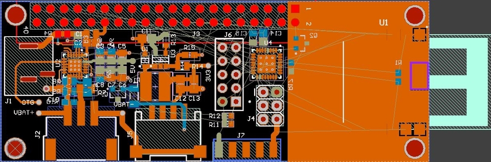
- fit on a 30mm X 80mm dual layer PCB
- ability to terminate power to the Raspberry Pi if needed
- ability to determine approximate charge level
- determine if powered from battery or wall-wart
- 12V, 3.5A DC input
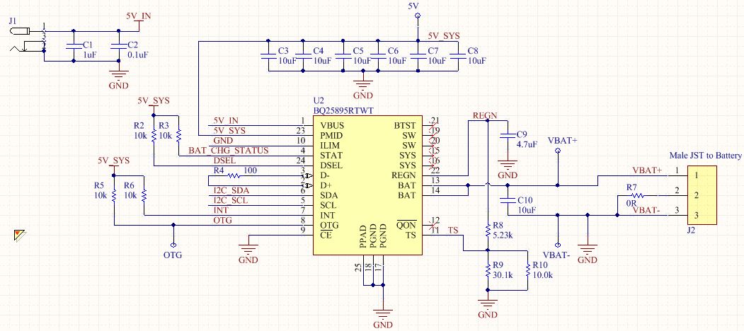
I did a little research and found the perfect chip for this project; the Texas Instruments BQ25895. This is a great little PMIC (power management integrated circuit) that is jam packed full of features that solve nearly all of the power requirements in a single package solution. The main features that caught my attention were:
- output up to 3.1A at 5V on the output via a boost converter @ 1.5MHz switching
- an I2C interface to a host (the RPi)
- ability to dynamically swap power-sources (battery or DC input)
- battery temperature monitoring
- auto-detect USB SDP, CDP, DCP etc. (USB BC1.2 standard)
- +/- 0.5% charge voltage regulation
- small footprint (4mm x 4mm)
The high switching speeds on the boost converter means I could use a smaller inductor (more on this later), which is handy on projects that have very limited real estate such as this. The I2C interface allows for changing the power systems characteristics, TI’s PowerPath is perfect for making small UPSs, and battery protection/monitoring is critical for safety (fire is a no-no).
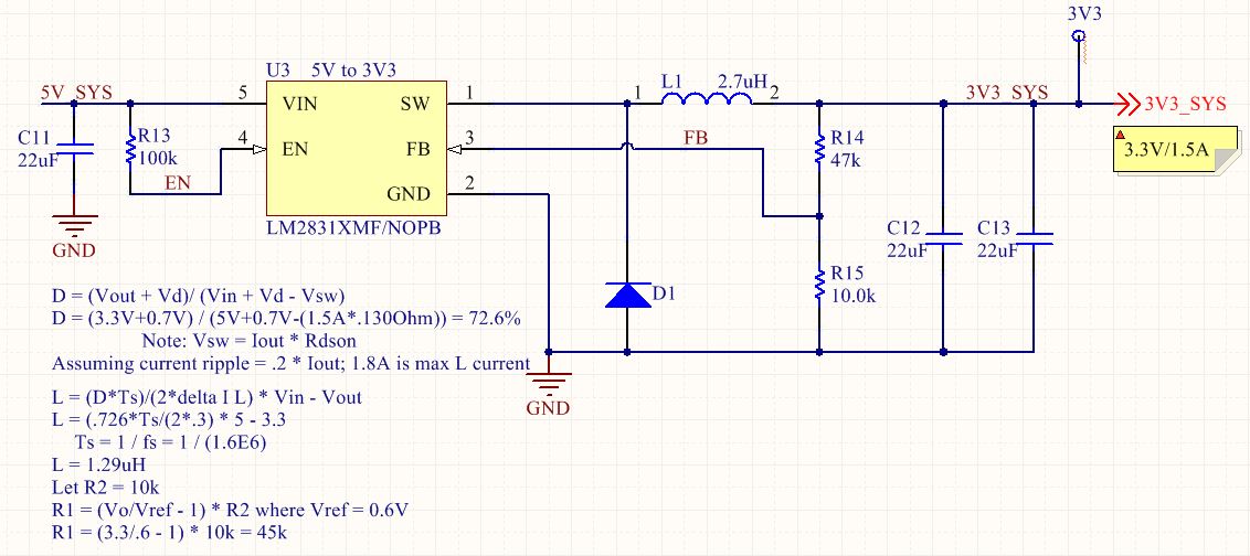
The BQ25895 combined with a 5V -> 3V Buck converter is sufficient to meet all of our power requirements for this little project. For this conversion, I chose to use the TI LM2831 to provide the 3.3V output and supply up to 1.5A.
Achieving the 3.3V output from the LM2831 is as easy as following the datasheet Texas Instruments supplies. I have provided my equations used to calculate the values for the input/output capacitors, inductor, diode and feedback resistors onto the schematic below.
With these two small chips, I can fulfill all of the power requirements my customer asked for in a cost effective, low part count solution. In the next post, I’ll explain some of the features this PMIC has, and how they’re useful.